We're here to help
Talk to an expert today.
Our friendly team of highly trained specialists will quickly assist you.
Description
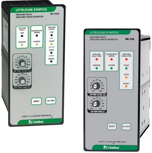
The SE-134C/SE-135 is a microprocessor-based, combination ground-wire monitor and ground-fault relay for resistance-grounded or solidly grounded systems. It continuously monitors the integrity of the ground conductor to protect portable equipment from hazardous voltages caused by ground faults. The SE-134C/SE-135 is field proven in monitoring trailing cables on large mobile equipment such as drag-lines, mining shovels, shore-to-ship power cables, dock-side cranes, stackerreclaimers, submersible pumps, and portable conveyors.
Features & Benefits
Adjustable pickup (0.5-12.5 A for SE-CS10) (2 - 50 A for SE-CS40)
Unit can be used on a wide variety of trailing cable applicationsAdjustable time delay (0.1-2.5 s)
Adjustable trip delay for quick protection and system coordinationOutput contacts
Separate annunciation of ground-fault and groundcheck faultsGround-check LED indication
Indication of open or short ground-check wire makes it easier to find faultsCT-loop monitoring
Alarms when CT is not connectedHigh-induced-ac rejection
Makes unit suitable for applications with high voltages and long cablesDFT (Harmonic) filter
Prevents false operationZener-characteristic termination assembly
Provides reliable ground-check loop verificationFail-safe circuits
Ensures ground-check and ground-fault circuits remain safe even in the event of equipment failureConformal coating
Additional coating protects circuit boards against harsh environmentXGC option
Increases maximum cable length for ground-check monitoring (10 km typical)
Specifications
- IEEE Device Numbers: Checking or Interlocking Relay (3GC), Ground fault (50G/N, 51G/N)
- Input Voltage: 65-265 Vac; 85-275 Vdc; 18-72 Vdc
- Dimensions: H 213 mm (8.4"); W 99 mm (3.9"); D 132 mm (5.2");
- Trip Level Settings: 0.5 -12.5 A for SE-CS10, 2 - 50 A for SE-CS40
- Trip Time Settings: 0.1-2.5 s
- Contact Operating Mode: Selectable fail-safe or non-fail-safe
- Harmonic Filtering: Standard feature
- Test Button: Standard feature
- Reset Button: Standard feature
- Output Contacts: Isolated Form A and Form B, Two Form C
- Approvals: CSA certified, UL Listed (E340889), C-Tick (Australia)(3), CE(3)
- Conformally Coated: Standard feature
- Warranty: 5 years
- Mounting: Panel, Surface
- GC Trip Resistance: 28Ω (Standard), 45Ω (XGC Option)
Ordering Information
| ORDERING NUMBER | OPTION | POWER SUPPLY | COMM |
| SE-134C | Blank or XGC | 0=120/240 VAC/VDC 1=24/48 Vdc (1) | 0=None |
| SE-135 | Blank or XGC | 0=120/240 VAC/VDC 1=24/48 Vdc (1) (2) | 0=None3=Ethernet (1) |
| ACCESSORIES | REQUIREMENT |
| SE-CS10 Series | Required |
| SE-CS40 Series (for SE-135) | Optional |
| SE-TA6A Series (for SE-134C) | Required |
| SE-TA12A/SE-TA12B Combination (for SE-134C) | Optional |
| SE-TA12A Series (for SE-135) | Required |
| SE-IP65CVR-G | Optional |
| RK-132 | Optional |
| PPI-600V | Optional |
Accessories
SE-CS10 or SE-CS40 Series Ground-Fault Current Transformer
Required zero-sequence current transformer detects ground-fault current.
SE-TA6A Series, SE-TA12A Series Termination Assembly
Required termination assembly; temperature compensated.
We're here to help
Talk to an expert today.
Our friendly team of highly trained specialists will quickly assist you.
We promise to respond within 4 business hours (AEST).
Or you will receive $100 off your next purchase. Read how it works.

Premium brands
Our brands are carefully selected and have a great track record of quality, reliability and safety.

Years of experience
Since being established in 1996, our company has been synonymous with great customer service.

Customers served daily
Fuseco has strong relationships with many clients from a wide range of industries.

Reply in 4 Hours
Related Resources
Top FAQs
A protection relay is a device that receives inputs typically from current transformers CT’s (but can be other sources) and then compares these inputs to set levels. If these inputs exceed the set levels a protection relay can then provide that information via display or indication, feed that information to other electronic control devices or it can be connected to a circuit breaker to isolate power.
Yes, currently Fuseco can offer both earth leakage and NER relays that are compliant to AS2081:2011. The relay manufacturer (Littelfuse) is also currently in the final stages of development for an AS2081:2011 compliant continuity relay that we expect to release in the near term.
An arc fault is a type of electrical fault that results from the breakdown of an insulating medium between two conductors where the energy is enough to sustain an arc across the insulator (often air) and can cause extreme amounts of light (arc flash), immense heat upwards of 19,000 degrees, and a resulting explosive pressure wave (arc blast). By using a relay that has optical sensors we can detect the flash of light the emanates from an Arc Flash and within 1 msec send a signal to a breaker to interrupt power. Because of the immense energy being released by an Arc Flash reaction time is critical. It can be seen on the graph that with a relay reaction time of only 1 msec (+ circuit breaker reaction time) we can interrupt power before the Arc Flash can result in critical damage.
An arc-flash happens when electric current flows through an air gap between conductors. There are several ways this can happen but the most common occurrence is when conductor insulation is worn or broken down.
The most important aspects of arc-flash relays are:
- reaction time
- trip reliability
- ease of installation
- sensor flexibility
- software
- sensor design
- avoidance of nuisance tripping
- scalability
To gain a deeper understanding of which features to consider when selecting an arc-flash relay please refer to the downloadable application guides.
Arc-flash relays are a necessary component in an electrical cabinet because they reduce the amount of incident energy in the system. While an arc-flash relay cannot prevent an arc flash from happening, it will protect critical assets and workers’ safety by reducing the severity of the flash. An arc-flash relay is an integral part of an arc-flash protection scheme that can minimize damage, and save money, time, and lives.
Three phase power systems are most often solidly earthed, however by using a Neutral Earthing Resistor (NER) a power system can be resistance earthed. This is done so that if an earth fault were to occur the amount of fault current will be limited by the NER resistance. One potential problem with a resistance earthed system is; what happens if the NER goes open circuit due to damage? If this were to happen the power system has now changed from a resistance earthed system to a system with no earth reference (floating). Now the NER is no longer restricting the amount of fault current and other devices that rely on an earth reference in order to operate, cannot do so. By using a NER monitoring relay the resistance and integrity of a NER can be continually monitored to detect for any variance in the NER resistance or integrity.
An earth fault can occur as a result of inadvertent contact between and energized conductor and earth or equipment frame. There can also be earth leakage from a system without “inadvertent contact”. This type of fault can be called capacitive earth leakage and it is caused by a capacitive effect between a high power conductor and earth. Small amount of earth leakage current can occur as a result of this capacitive effect. Whether it is smaller amounts current from capacitive earth leakage or larger amounts of current from direct inadvertent contact an earth leakage relay can detect this fault current. In all electrical circuits, current returns to its source. An earth fault relay can use a zero sequence CT to monitor phase current to ensure that all current coming from the source returns on those same conductors or it can monitor current in the connection between transformer neutral and earth. By either method the earth leakage relay detect any lost current to earth.
our brand portfolio

Applicable Industries

Hi Tim, just wanted to thank you and the Fuseco team for your help. You've managed to help us solve some nagging issues here and the Littelfuse SE-330AU relay installation has saved us a lot of time. Thanks!
Mark Sherman
PGS Silver, Queensland

Just wanted to send a note of thanks to you guys. When it comes to relays, your advice & service is high level & appreciated. Cheers.
Jesse Marshall
Newcrest WA

The Littelfuse SE-701 & the CT's are functioning well. Thanks guys, really appreciate your help. Good to work with people you can rely on.
Cliff Peligro
Alpha Coal, Queensland
Technical Support
Our experts are all pre-eminent leaders in electrical products who provide excellent support in their areas of expertise.
Technical supportTalk to an expert
Our friendly team are highly trained product experts who really enjoy helping customers find what they need.
call 1300 387 326Enquire by email
We promise to respond within 4 business hours (AEST) or you will receive $100 off your next purchase.
Enquire now
